Build a WiFi camera robot, then drive it with MQTT and Node-RED
A step-by-step workshop for the ESP32 Camera 4WD Robot Car Kit. Every lab has code you can copy with one click. Work through the modules in order; each one builds on the last.
Fill these in once. Every code block on this site updates with your values, so the code you copy is ready to upload. This is the classroom network (LAN) version: the broker and Node-RED run on a server in the room. Your instructor gives you the server IP (it changes from network to network) and an MQTT username and password. Teams share one login: use the login of the student whose robot it is. Your Node-RED has its own, different username and password: type those on the Node-RED sign-in page, not here.
Saved in this browser only.
What's in the kit
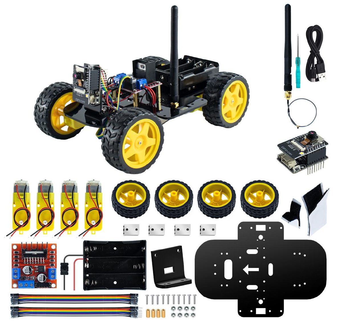
Kit contents (from the kit manual)
Part
Qty
What it does
ESP32-CAM board + USB adapter
1
The brain: WiFi, Bluetooth and a camera
L298N motor driver
1
Lets the small ESP32 signals switch big motor currents
TT DC gear motors + wheels
4
Move the robot (wired as a left pair and a right pair)
External WiFi antenna
1
Longer WiFi range
18650 Li-ion batteries
3
About 11.1–12.6 V for the motors and board (often bought separately)
USB cable
1
Uploads code from your PC
Safety
18650 batteries store a lot of energy. Insert them the right way round (check + and −), never short the terminals, switch the robot off when you are not using it, and only charge them in a proper 18650 charger with someone watching.
How to use this site
Copy
The yellow Copy button copies a whole code block. Paste it into a new Arduino sketch with Ctrl+V.
Download
Download gives you a .zip with a ready-made sketch folder. Unzip it and open the .ino in Arduino IDE.
Tick it off
Press Mark done when a lab works. Your progress shows in the course map on the left.
You need three things before you can upload code: the Arduino IDE, the ESP32 board package, and the CH340 USB driver. Do this once per computer.
STEP A
Install Arduino IDE 2
≈ 10 min
Go to arduino.cc/en/software and download Arduino IDE 2.x for your system (Windows, macOS or Linux).
Run the installer and accept the defaults. If Windows asks to install USB drivers, click Install.
Open Arduino IDE. You should see an empty sketch with setup() and loop().
Tip
Already have an old Arduino IDE 1.x? The kit manual recommends uninstalling it and installing the latest version.
STEP B
Add ESP32 boards
≈ 10 min
Click the Boards Manager icon on the left side (or Tools › Board › Boards Manager…).
Type esp32 in the search box. Find esp32 by Espressif Systems.
Pick version 3.1.0 (the version the kit was tested with; newer 3.x versions also work with this site's code) and click INSTALL. It downloads a lot, so give it a few minutes.
Wait for "Successfully installed platform esp32" in the Output panel.
esp32 doesn't show up in the search?
Open File › Preferences, paste this URL into Additional boards manager URLs, click OK, then search again.
STEP C
Install the CH340 USB driver
≈ 5 min
The USB adapter under the ESP32-CAM uses a CH340 chip to turn USB into serial. Windows needs a driver for it, otherwise no COM port appears.
Download CH341SER from the chip maker's site: wch-ic.com › CH341SER (Windows). Mac and Linux usually work without a driver.
Plug the ESP32-CAM adapter into your PC with the USB cable, run the installer and click INSTALL. You should see "Driver install success!"
Open Device Manager (search for it in the Start menu) › Ports (COM & LPT). You should see USB-SERIAL CH340 (COMx). Remember the number.
No port?
Try a different USB cable. Many cables only carry power, not data.
Try another USB socket or another computer.
Uninstall the driver, restart the PC, and install again.
STEP D
Your upload checklist
use every time
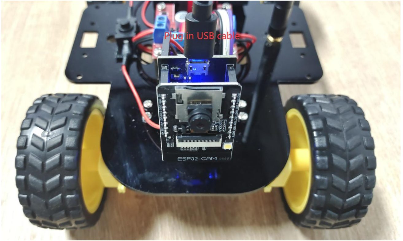
Plug the USB cable into the adapter board under the ESP32-CAM.
Setting
Choose
Tools › Board
esp32 › AI Thinker ESP32-CAM
Tools › Port
The COMx you saw in Device Manager
Serial Monitor speed
115200 baud
Upload
Click the round → button and wait for "Done uploading"
Upload fails?
"Failed to connect… wrong boot mode": hold the IO0 button on the adapter, press and release RST, release IO0, then click Upload again. Press RST after "Done uploading".
Brownout / keeps resetting: your PC's USB port can't supply enough power. Switch the robot's battery on while uploading (wheels off the table!).
Port is greyed out: close the Serial Monitor in any other window, then try again.
Get to know the board before it drives anything. You'll print messages, blink LEDs, scan for WiFi and stream live video.
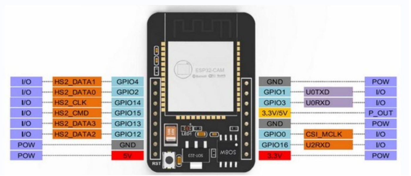
ESP32-CAM pins. The robot uses IO12, IO13, IO14, IO15 for the motors.
Board tour
Chip
ESP32 (dual core, up to 240 MHz), 4 MB PSRAM
Wireless
WiFi 802.11 b/g/n + Bluetooth 4.2 / BLE
Camera
OV3660 on this kit (3 MP)
GPIO 4
White flash LED (very bright)
GPIO 33
Small red LED, on when LOW
GPIO 12–15
Free pins → motor driver
RST button
Restarts your program
LAB 1
Hello ESP32-CAM
≈ 10 min
Goal: upload your first sketch and read messages from the board in the Serial Monitor.
In Arduino IDE choose File › New Sketch, delete everything, and paste the code below.
Check Board = AI Thinker ESP32-CAM and the right Port, then click Upload.
Open Tools › Serial Monitor and set the speed to 115200 baud. Press RST on the board if the screen is empty.
You should see
"Hello from my ESP32-CAM!" followed by the chip model, CPU speed, PSRAM size (about 4096 KB) and MAC address every second.
Try this
Change delay(1000) to delay(250). What happens? Write your own name into the first message.
LAB 2
Blink the red LED
≈ 10 min
Goal: control an output pin with digitalWrite(). This LED is "active LOW", which surprises everyone the first time.
You should see
The tiny red LED on the back of the ESP32-CAM blinks twice per second.
Try this
Make it blink an SOS: three short, three long, three short.
LAB 3
Fade the flash LED with PWM
≈ 15 min
Goal: learn PWM, the same trick we'll use later to control motor speed.
PWM switches a pin on and off thousands of times per second. The duty (0–255) is how much of each cycle the pin is ON. 0 = always off, 128 = half the time, 255 = always on. The LED (or motor) only "feels" the average.
Eyes
The flash LED is extremely bright at full power. Keep MAX_BRIGHTNESS low and don't look straight into it.
Try this
Make the LED "breathe" faster or slower by changing delay(20).
LAB 4
WiFi scanner
≈ 10 min
Goal: first wireless lab. See every network around you and how strong it is.
You should see
A numbered list of networks every 5 seconds. Find your classroom WiFi. Is the signal better than −70 dBm?
Try this
Screw on the external antenna and compare the numbers. (Some boards need a tiny jumper resistor moved to use the antenna; ask your instructor.)
LAB 5
Live camera web server
≈ 20 min
Goal: stream live video from the robot's camera to a browser on the classroom WiFi. This uses an example that comes with the ESP32 package.
Open File › Examples › ESP32 › Camera › CameraWebServer.
Find the Select camera model lines (in the main tab, or in the board_config.h tab on newer versions). Switch off the model that's on and switch on AI_THINKER:
Find the WiFi lines near the top of the main tab and replace them with:
Upload. Open the Serial Monitor (115200) and press RST. Wait for Camera Ready! Use 'http://192.168.x.x' to connect.
On a phone or laptop on the same WiFi, open that address and click Start Stream.
Notice
Here the ESP32 joins an existing WiFi network (station mode). In Module 4 the robot makes its own hotspot (access-point mode). Both are useful.
Problems?
"Camera init failed": the camera model is wrong, or the ribbon cable is loose. Reseat it gently.
"Sketch too big": Tools › Partition Scheme › Huge APP.
Dots forever after "WiFi connecting": check the WiFi name/password in your team settings (they are case-sensitive). ESP32 only uses 2.4 GHz WiFi.
The ESP32 can't power a motor directly: its pins give a few milliamps at 3.3 V, and a motor wants hundreds of milliamps. The L298N driver sits in between, like a set of electronic switches.
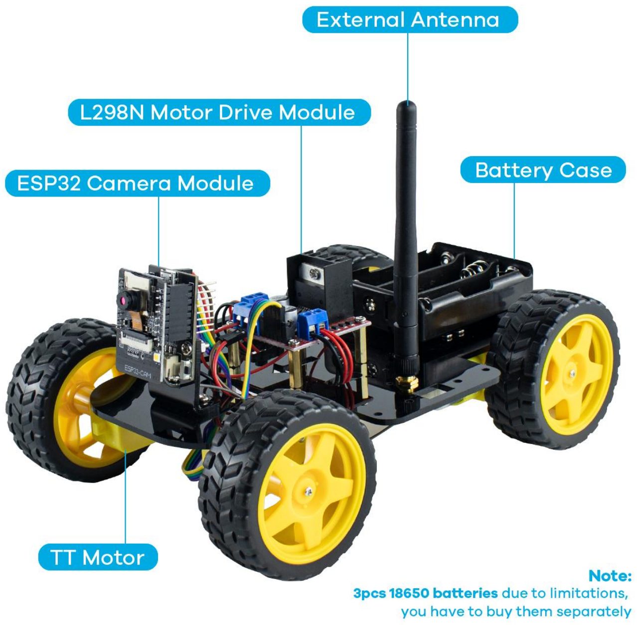
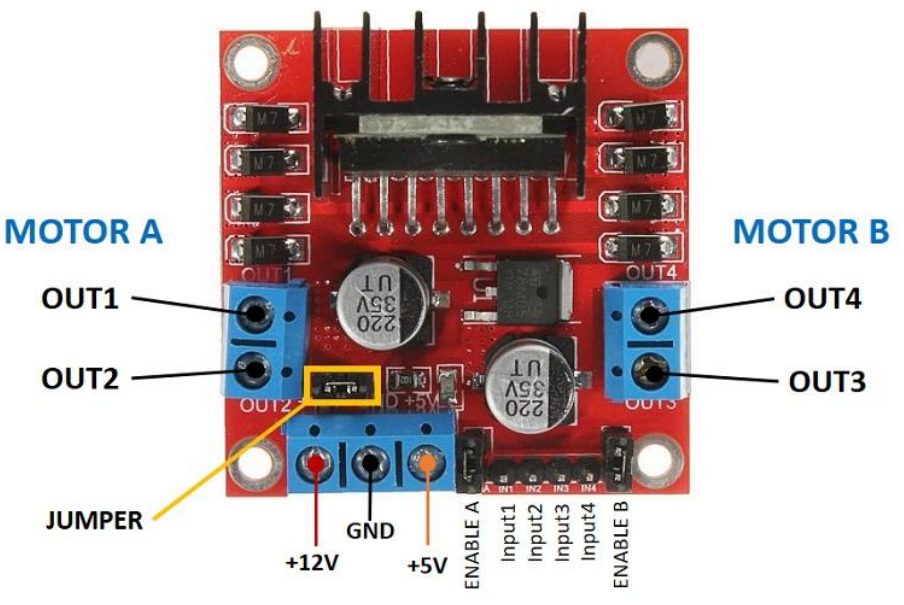
The assembled robot and its main parts.L298N pins. Keep the 5 V jumper and the ENA/ENB caps in place.
BUILD
Assemble the robot and motors
≈ 45 min
Goal: put the chassis, the four motors, the wheels, the camera holder, the L298N and the battery case together using the Thinklab assembly guide. Keep the batteries out until everything is wired.
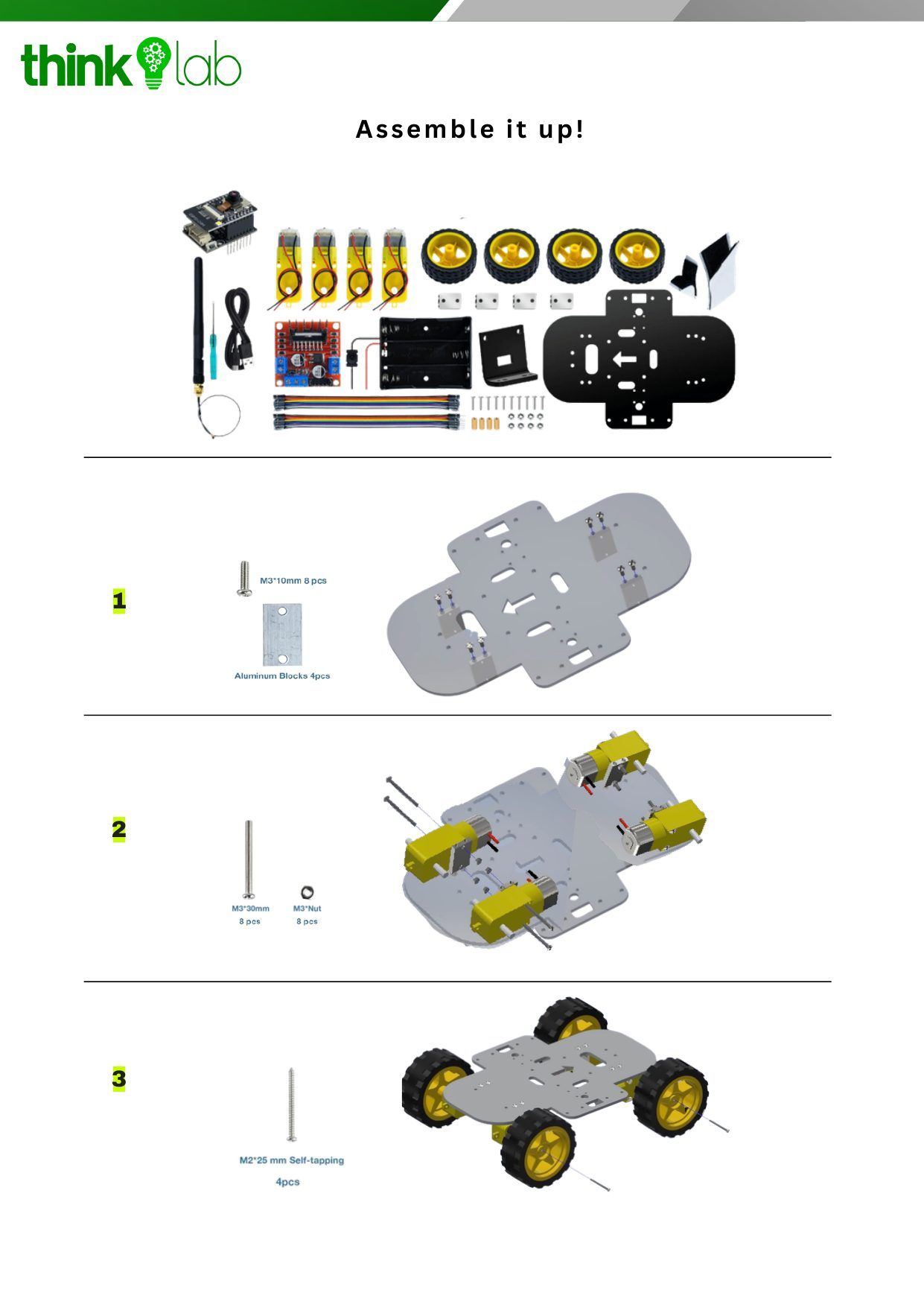
Steps 1–3 (page 1): screw the 4 aluminium blocks to the chassis (M3×10 mm), fix the 4 motors to the blocks (M3×30 mm screws + nuts), then push on the wheels and secure them (M2×25 mm self-tapping).
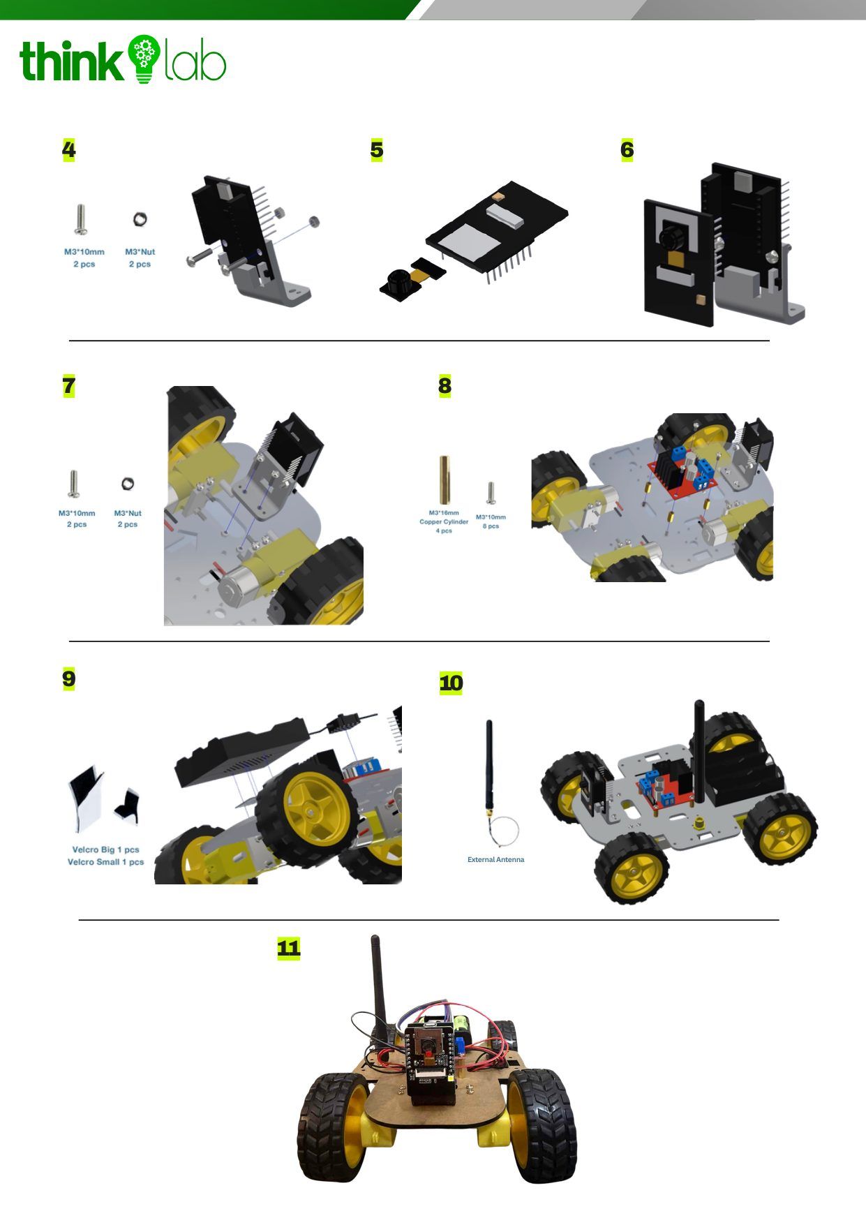
Steps 4–7 (page 2): mount the camera holder, fit the camera ribbon into the ESP32-CAM, plug the ESP32-CAM onto its adapter, and fix the holder to the front of the chassis.
Steps 8–11 (page 2): raise the L298N on the 4 copper spacers, stick the battery case on with Velcro, screw on the external antenna and connect it to the ESP32-CAM.
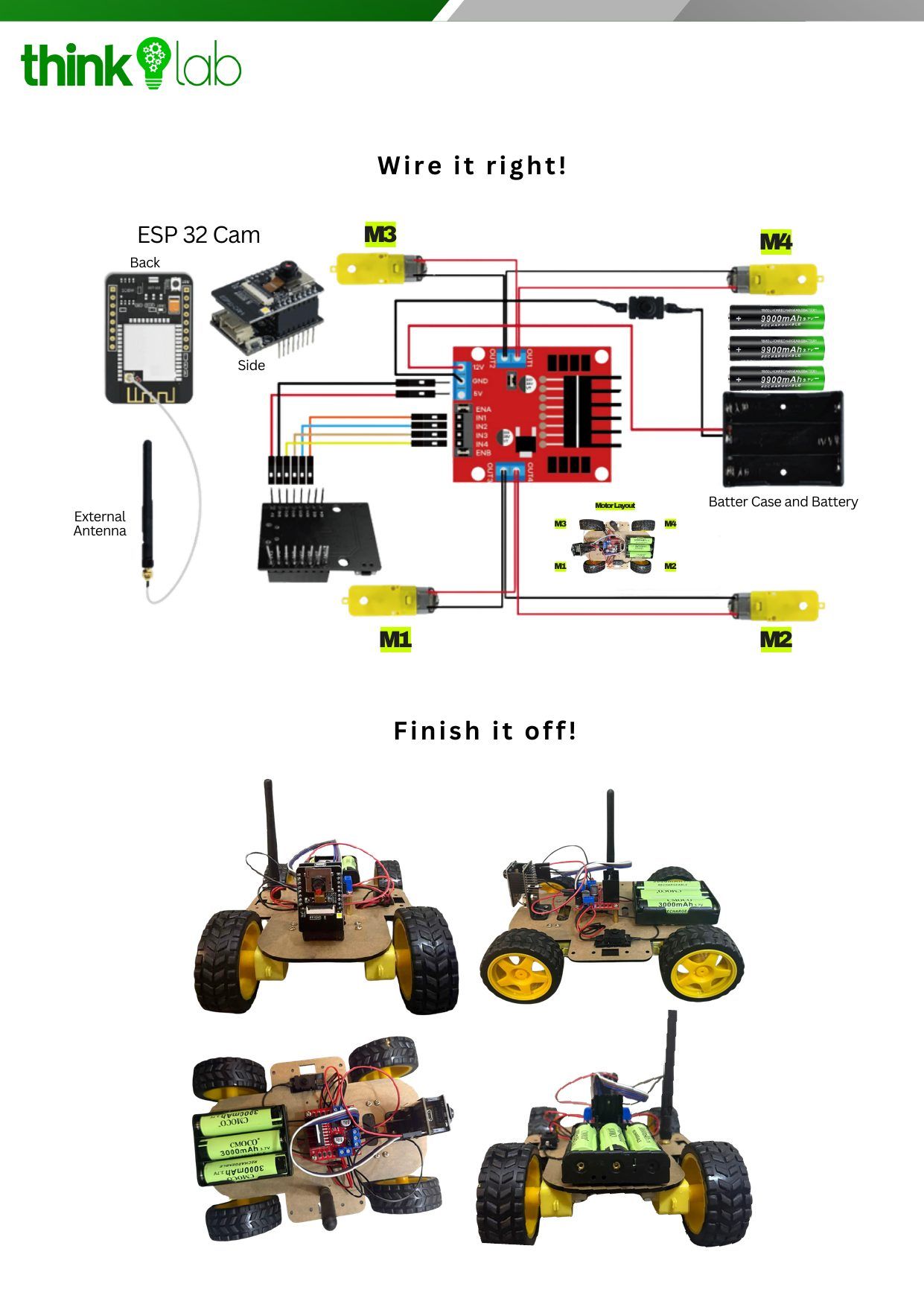
Wiring (page 3): continue with Wire the robot below. It matches the "Wire it right!" diagram.
Tip
Tap a page to open it full size. On a phone, Open PDF lets you zoom in on the small screw labels.
Page 1 · Assemble it up! (steps 1–3)Page 2 · Steps 4–11Page 3 · Wire it right! and Finish it off!
BUILD
Wire the robot
≈ 30 min
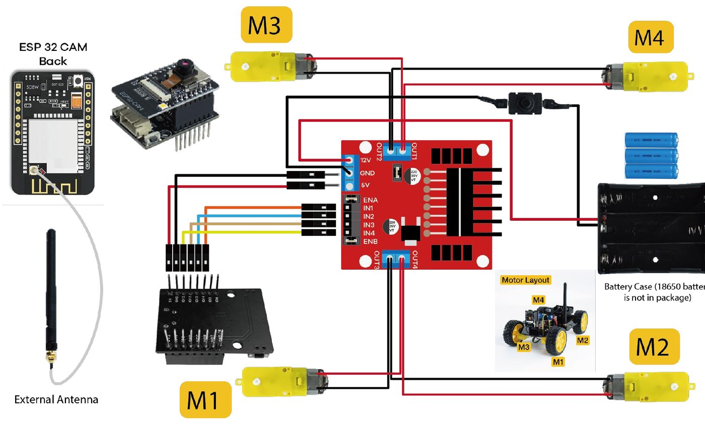
Goal: connect the battery, the L298N, the four motors and the ESP32-CAM exactly like the kit diagram. Batteries OUT while you wire.
Kit wiring diagram. Two motors share each L298N output: one pair per side.
From (ESP32-CAM adapter)
Wire in diagram
To (L298N)
Job
5V
red
5V
Powers the ESP32-CAM from the L298N's regulator
GND
black
GND
Shared ground (must be connected!)
IO14
orange
IN1
Motor A (OUT1/OUT2) direction
IO15
blue
IN2
Motor A (OUT1/OUT2) direction
IO13
tan
IN3
Motor B (OUT3/OUT4) direction
IO12
yellow
IN4
Motor B (OUT3/OUT4) direction
Battery +
red, via switch
12V
Motor power (3 × 18650 ≈ 11.1–12.6 V)
Battery −
black
GND
Battery ground
Quick test
The kit comes with its firmware already loaded. Insert the batteries, lift the robot, switch on and press RST: the motors briefly run. That tells you the motor wiring is alive.
How the L298N makes a motor turn
Each motor channel has two inputs. Make one input "on" and the other "off" and the motor spins one way; swap them and it spins the other way; both off and it stops. In this kit the ENA/ENB jumpers stay on (channels always enabled), and the code sends PWM to the IN pins to set the speed. So a "1" in the table below really means "PWM at the current speed".
Direction explorer
Click a direction to see which pins are driven and how each side's wheels turn.
Move
IO13 IN3
IO12 IN4
IO14 IN1
IO15 IN2
Forward
0
speed
0
speed
Backward
speed
0
speed
0
Turn left
speed
0
0
speed
Turn right
0
speed
speed
0
Stop
0
0
0
0
LAB 6
Motor test
≈ 15 min
Goal: check that every motor turns the right way. This replaces the kit firmware; you can re-upload it later from Module 4.
Put the robot on a box or cup so the wheels hang in the air.
Upload the sketch. Switch the battery on. After 2 seconds it runs forward, backward, left, right, once.
Watch each wheel. Press RST to repeat.
What you see
Fix
One wheel turns backwards on "Forward"
Swap that motor's two wires in its OUT terminal.
A whole side turns backwards
Swap the two wires of that side's OUT terminal (or swap IN1↔IN2 / IN3↔IN4).
"Left" turns right
Swap the pin numbers of LEFT_* and RIGHT_* in the code.
setMotors(l0, l1, r0, r1) writes one PWM value to each of the four L298N inputs. Every movement is just a different pattern of those four numbers, exactly like the table above.
LAB 7
Drive from your PC keyboard (USB)
≈ 15 min
Goal: your first "remote control", through the USB cable. The PC sends letters, the ESP32 turns them into movements.
Upload, open the Serial Monitor at 115200, robot still on its box.
Type w and press Enter. The wheels spin forward until you send x.
Try this
Add a b key that blinks the flash LED, or a q key that spins on the spot for exactly one second.
Now we cut the cable. The robot runs a small web server, and any phone or laptop browser becomes the remote. First with the kit's own firmware (with live camera), then with code you write yourself.
PART A
Drive with the kit firmware
≈ 15 min
Goal: use the factory program: camera stream plus drive buttons. If you uploaded Labs 1–7, re-upload the kit code first (Part B).
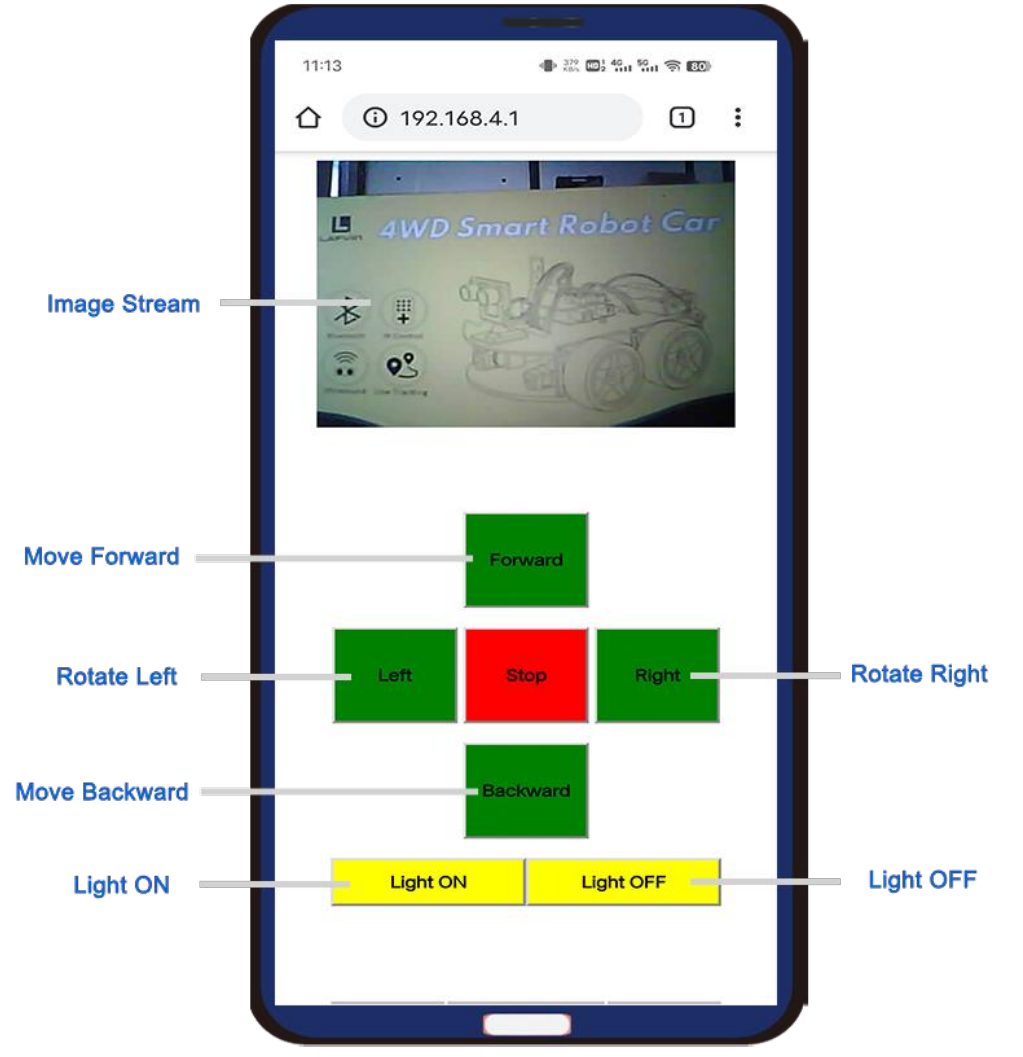
Turn on the power switch. The small red LED on the ESP32-CAM lights up when its WiFi is ready. If not, press RST.
On your phone open WiFi settings and join ESP32-CAM Robot (no password).
Open a browser and go to 192.168.4.1.
Hold a green button to drive; release to stop. Yellow buttons switch the flash LED.
The kit's remote page.
Page won't load?
Turn mobile data off. Phones often send traffic over 4G/5G when the WiFi "has no internet".
Check you joined the right robot's WiFi.
Low batteries cause random resets. The total should be above 11.1 V.
Every button is just a URL
The remote page simply opens these addresses in the background. Try typing them into a PC browser that's connected to the robot's WiFi:
PART B
Re-upload the kit firmware (and rename its WiFi)
≈ 15 min
Goal: put the camera robot program back on the board, with a WiFi name that's unique to your team, so twenty robots called "ESP32-CAM Robot" don't confuse everyone.
Kit main codeESP32_Camera_4WD_Robot_Car_OV3660_V3: .ino + app_httpd.cpp + camera_index.h
Unzip it. Keep all three files in the folder ESP32_Camera_4WD_Robot_Car_OV3660_V3.
Open the .ino file. All three files appear as tabs.
Change line 9 so the hotspot carries your team name:
Board AI Thinker ESP32-CAM, your Port, Upload. Then repeat Part A with your new WiFi name.
LAB 8
Build your own web remote
≈ 30 min
Goal: write the web server yourself: hold-to-drive buttons for phones, WASD keys for PCs, a speed slider, and a safety stop.
Upload. The Serial Monitor shows Hotspot: Robot-student01.
Join that WiFi (password robot1234) and open 192.168.4.1.
Phone: hold the arrows. PC: hold WASD or the arrow keys.
Address
What the ESP32 does
/
Sends the remote page (HTML stored in PAGE)
/cmd?c=forward
Drives. While you hold a button, the page repeats this every 200 ms
/speed?v=200
Sets PWM speed 0–255
/light?on=1
Flash LED on (0 = off)
Why the failsafe?
If your phone locks or walks out of range, the "stop" message may never arrive. The robot stops itself when it hears nothing for 0.6 s. Real robots always have a failsafe like this.
Try this
Add a "Spin" button that sends /cmd?c=left, or change the button colours in the <style> part of PAGE.
With a web remote, your phone talks straight to one robot. With MQTT, everything talks to a central broker, and the broker passes messages on. Our class broker runs on the classroom server at 192.168.1.9, port 1883. It only works inside the classroom network: your robot, your laptop and your phone must all be on the classroom WiFi. Every student has a login and a private topic folder; the teacher can see everything.
Word
Meaning
In our robot
Broker
The post office. Receives every message and forwards it.
192.168.1.9, port 1883 (classroom server)
Topic
The address on the envelope, like a folder path
students/student01/cmd
Login + ACL
Username and password. The broker only lets you use your own folder
students/student01/#
Publish
Send a message to a topic
Node-RED publishes forward:800
Subscribe
Ask the broker for every message on a topic
The robot subscribes to its /cmd topic
Retained
The broker keeps the last message for newcomers
/status stays "online" or "offline"
Last Will
A message the broker sends if a client vanishes
Robot loses power → broker publishes "offline"
Wildcards
+ = one level, # = everything below
students/+/status (teacher only)
Your connection settings
Topic rules
You can only publish and subscribe inside students/student01/. The broker does not show an error for other topics (like test, # or another student's folder): the message simply never arrives. Always double-check the topic.
Network
LAN only. The robot, your laptop and your phone must be on the classroom WiFi (2.4 GHz for the robot). No internet is needed. Use the server IP 192.168.1.9 from the Start page: it changes when the server joins a different network, so update it there and copy the code again.
Instructor: the classroom server
One server on the classroom network runs Mosquitto on port 1883 (username + password, no TLS) and one Node-RED per student on ports 2001–2030 (student01 → 2001 … student30 → 2030).
Find the server's IP on each new network (hostname -I on Linux, ipconfig getifaddr en0 on Mac) and give it to the students. They type it once on the Start page.
The broker's ACL lets each studentNN use only students/studentNN/#; the teacher login can read students/#. Students can test this with the "try to listen to another student" step below.
The WiFi access point must allow devices to talk to each other: turn client / AP isolation off (often on by default on guest networks).
Robots publish online/offline on students/<user>/status and JSON telemetry (speed, rssi, uptime) on /telemetry.
Watch every student from a terminal:
WARM-UP
Publish and subscribe with MQTT Explorer
≈ 10 min
Goal: see MQTT messages with your own eyes before the robot joins in. Your laptop must be on the classroom WiFi.
Click + for a new connection and fill in: Name Class broker · Encryption (tls) OFF · Protocol mqtt:// · Host 192.168.1.9 · Port 1883 · Username student01 · Password YOUR_MQTT_PASSWORD. No certificate is needed on the classroom network.
Click ADVANCED. Delete # and $SYS/# with the trash icons (students may not use them), add students/student01/# with + ADD, then BACK › SAVE › CONNECT.
In the Publish panel, topic students/student01/hello, message hi, click Publish. A students › student01 › hello branch appears in the topic tree on the left.
Your teacher sees your message at the same moment. That's the "many screens, one broker" idea. You can't see other students' folders; only the teacher can.
WARM-UP
Option: publish and subscribe from the terminal
≈ 10 min
Goal: the same test as MQTT Explorer, with terminal windows: one subscribes (listens), one publishes (sends). The server IP, your username, password and topic folder are already in every command, so just copy and paste. Your laptop must be on the classroom WiFi.
Open Terminal (Cmd+Space, type Terminal) and install the Mosquitto tools with Homebrew (needs internet once):
Window 1 – listen. Paste this and leave the window open. It waits for messages in your folder.
Window 2 – send. Open a second window and paste:
Window 1 prints students/student01/hello hello from my laptop. That's a full round trip through the classroom broker.
Send a number too. You'll use this topic again in the Node-RED temperature example.
Privacy test. In a third window, try to listen to another student's folder. You should receive nothing, even when they publish: the broker only lets you into your own folder.
Stop listening with Ctrl+C.
Download the Windows installer from mosquitto.org/download (mosquitto-2.x-install-windows-x64.exe). In the installer, untick "Service" and keep the folder C:\Program Files\mosquitto.
Open Windows PowerShell (normal, not as administrator) and go to the Mosquitto folder. Do this in every PowerShell window you open:
Window 1 – listen. Paste this and leave the window open. It waits for messages in your folder.
Window 2 – send. Open a second window, run the cd line again, and paste:
Window 1 prints students/student01/hello hello from my laptop. That's a full round trip through the classroom broker.
Send a number too. You'll use this topic again in the Node-RED temperature example.
Privacy test. In a third window, try to listen to another student's folder. You should receive nothing, even when they publish: the broker only lets you into your own folder.
Stop listening with Ctrl+C.
Open a terminal (Ctrl+Alt+T on Ubuntu) and install the Mosquitto clients (needs internet once):
Window 1 – listen. Paste this and leave the window open. It waits for messages in your folder.
Window 2 – send. Open a second window and paste:
Window 1 prints students/student01/hello hello from my laptop. That's a full round trip through the classroom broker.
Send a number too. You'll use this topic again in the Node-RED temperature example.
Privacy test. In a third window, try to listen to another student's folder. You should receive nothing, even when they publish: the broker only lets you into your own folder.
Stop listening with Ctrl+C.
Window 1 should look like this:
You see
Fix
Connection Refused: not authorised or CONNACK (5)
Wrong MQTT username or password (case-sensitive). Check the Start page, and don't mix it up with your Node-RED password
Error: Connection refused, timed out or No route to host
Wrong server IP, or your laptop is not on the classroom WiFi. Check the IP on the Start page with your instructor
Connected, but the message never arrives
The topic must start with students/student01/. Other topics are silently dropped
Windows: '.\mosquitto_sub.exe' is not recognized
Run the cd "C:\Program Files\mosquitto" line first
A quote> prompt and nothing happens
A ' quote got lost while copying. Press Ctrl+C and paste again with the Copy button
Keep window 1 open
Leave the listener running during Lab 9: you'll see the robot's status, telemetry and every command arrive live.
LAB 9
Turn the robot into an MQTT robot
≈ 30 min
Goal: the robot joins the classroom WiFi, logs in to the classroom broker, obeys commands on its /cmd topic and reports its telemetry.
Install the library: Sketch › Include Library › Manage Libraries…, search PubSubClient, install the one by Nick O'Leary.
Check sections 1 and 2 at the top of the code: WiFi name and password, MQTT username and password. They come from the settings on the Start page. The server IP comes from there too.
Upload, open the Serial Monitor. You should see WiFi OK then MQTT OK, listening on students/student01/cmd. The red LED on the board turns on when it's connected to the broker.
Test it
In MQTT Explorer, publish forward:1000 to students/student01/cmd. The robot drives for one second. Open /telemetry to see its JSON report and /status to see "online". Publish on / off to /led to switch the flash LED. Command-line fans (Mosquitto from the terminal warm-up) can use:
Windows PowerShell version
Safety built in
Plain forward stops by itself after 3 s (MAX_MOVE_MS).
If WiFi or the broker connection drops, the robot stops immediately.
rc = −2 ?
The robot can't reach the broker. Check the robot is on the classroom WiFi (2.4 GHz), that MQTT_HOST is the server IP 192.168.1.9 (update it on the Start page if the server changed network), and that the port is 1883.
rc = 4 or 5 ?
Wrong username or password. Both are case-sensitive. Fix them on the Start page, copy the code again and upload.
Next
In Module 6, the LED example (Lab 11) switches this robot's flash LED from a dashboard, and Lab 13 is a full control panel for it.
Node-RED lets you program by wiring boxes ("nodes") together in a browser. It speaks MQTT out of the box, and with Dashboard 2.0 it builds control panels that work on any phone or PC. You'll install the dashboard, build one by hand, try two MQTT examples, then drive the robot.
SETUP
Open your Node-RED and install Dashboard 2.0
≈ 10 min
Nothing to install on your laptop. Every student has their own Node-RED on the classroom server, one port each: student01 → port 2001 … student30 → port 2030. The links on this page use the server IP and Node-RED port from the Start page (student25 → port 2025). Your laptop or phone must be on the classroom WiFi.
Open your Node-RED editor. If it asks you to sign in, use your Node-RED username and password from your instructor. These are not your MQTT login.
Open the menu ☰ (top right) › Manage palette › Install tab, and search for:
Click install on @flowfuse/node-red-dashboard, then Install again to confirm. Wait for "Nodes added to palette", then click Close. (Installing needs the server to have internet. If it doesn't, your instructor installs Dashboard 2.0 beforehand.)
Check: the node list on the left now has a dashboard 2 section (button, text, switch, gauge, chart…).
Pick the right one
The search also shows node-red-dashboard (no @flowfuse/ in front). That is the old Dashboard 1.0, deprecated since June 2024. It won't work with these labs. Install only @flowfuse/node-red-dashboard.
Your own instance
Only open your address. Everyone on the classroom WiFi can reach every port, so a flow you deploy in someone else's editor changes their work.
Optional: run Node-RED on your own laptop instead (after class)
Install Node.js LTS from nodejs.org, then run these one at a time in Command Prompt (Windows) or Terminal (Mac/Linux). The editor is then at http://127.0.0.1:1880 and the dashboard at http://127.0.0.1:1880/dashboard.
LAB 10
Build your first dashboard by hand
≈ 25 min
Goal: understand how a dashboard is put together by adding a button, sections and pages yourself.
Part
What it is
In this lab
Base (ui-base)
The whole dashboard website. Only one per Node-RED
Robot Lab, at /dashboard
Page (ui-page)
A screen, listed in the dashboard's side menu
Home, Page 2
Group (ui-group)
A section: a card on a page that holds widgets
Controls, Messages, Fun
Widget
A node from the dashboard 2 palette: button, text, switch, gauge…
Say hello button, Last message text
1 · Add the dashboard base (once)
Every flow on this site shares one base, so you import it instead of making it. Copy, then ☰ › Import › paste › Import › Deploy. It only adds settings (you won't see new nodes on the canvas).
2 · A page, a section and a button
Click + at the top of the canvas to open a new, empty tab. Drag a button node from dashboard 2 onto it and double-click it.
Next to Group, choose Add new ui-group… and click the pencil ✎. Name the group Controls. This is your first section.
Still in the group window, next to Page choose Add new ui-page… and click the pencil ✎. Fill in Name Home, Path /home, UI Robot Lab, Theme Robot Lab theme. Click Add, then Add again in the group window.
Back in the button window: Label Say hello, Payload hello (type: string). Click Done.
Drag a debug node (common section) next to it and draw a wire from the button's right side to the debug node.
Click Deploy, then open your dashboard in a new tab:
Press Say hello on the dashboard. In the editor, open the Debug sidebar (bug icon, top right): hello appears.
UI says "Add new ui-base…"?
You skipped step 1. Click Cancel, import the dashboard base above, then try again. Don't make a second base: Dashboard 2.0 only allows one.
3 · A second section
Drag a text node (dashboard 2) onto the canvas and double-click it. Group: Add new ui-group… › ✎ › Name Messages, Page Home › Add.
Label Last message › Done. Wire the Say hello button to it as well, then Deploy.
On the dashboard, the Home page now has two cards. Press the button: Last message shows hello.
4 · A second page
Drag another button. Group: Add new ui-group… › ✎ › Name Fun, Page: Add new ui-page… › ✎ › Name Page 2, Path /page2, UI Robot Lab, Theme Robot Lab theme › Add › Add.
Label Hi from page 2, Payload hi from page 2 › Done. Wire it to the Last message text node. Deploy.
On the dashboard, open the side menu (☰, top left) and switch between Home and Page 2. Press the button on Page 2, then go back to Home: the message is there.
Dashboard 2.0 sidebar
In the editor's right sidebar, open the Dashboard 2.0 tab (use the ▾ next to the sidebar tabs if you don't see it). It shows the layout as pages › groups › widgets. You can add pages and groups there and drag them to change the order.
Try this
Change a group's Size (width) and watch the cards rearrange on a phone and a laptop.
Give the button an icon, e.g. hand-wave (Material Design icon names).
LAB 11
Example 1 · MQTT LED on/off
≈ 15 min
Goal: a dashboard switch publishes on / off to students/student01/led, and a subscription shows what was last sent. Your MQTT username, password and the classroom broker (server IP, port 1883) are already filled in.
Copy › ☰ › Import › paste › Import › Deploy. A tab Example - MQTT LED opens.
Under the MQTT nodes a green connected label appears. If it stays on "connecting", double-click an MQTT node › ✎ next to Server › Security tab, retype your MQTT username and password (not the Node-RED login) › Update › Done › Deploy.
Open the LED page of your dashboard (side menu, or this link):
The flow includes a test sensor that publishes a pretend temperature every 5 seconds, so the gauge moves and the chart grows straight away.
Got a real board publishing to students/student01/temp (for example an ESP32 with a sensor, or mosquitto_pub from the terminal warm-up)? Select the three test-sensor nodes, press Delete, and Deploy.
Already exist?
If Node-RED says some nodes already exist, click Replace. Those are the shared dashboard base and broker settings that every flow on this site uses.
How it works
mqtt in receives text like "27.4" → the to number function turns it into the number 27.4 and ignores anything else → the same message goes to the gauge, the text and the chart. The chart keeps the last hour.
Try this
Add a second gauge that shows the robot's WiFi signal: subscribe to /telemetry (output: parsed JSON object) and use msg.payload.rssi.
Make the LED from Example 1 switch on automatically when the temperature goes above 30 °C.
LAB 13
The robot application: a control dashboard
≈ 25 min
Goal: drive the Lab 9 MQTT robot from a real control panel with drive buttons, speed and step-time sliders, a light switch, a square dance and live status, from any phone on the classroom WiFi.
Make sure the robot is running the Lab 9 sketch and shows online. Import this flow and Deploy.
Each tap of an arrow moves the robot for the Step time set on the slider. STOP stops at once. Square dance sends eight timed moves.
Open the same address on your phone while it is on the classroom WiFi (mobile data won't work: the server is only on the LAN). In the phone browser choose Add to Home Screen to open it like an app.
Already exist?
If Node-RED says some nodes already exist, click Replace. Those are the shared dashboard base and broker settings that every flow on this site uses.
How it works
An arrow button sends forward → the add step time function turns it into forward:600 using the slider value it remembered in flow.stepMs → mqtt out publishes it to /cmd. The robot's telemetry JSON comes back through mqtt in → split status → four text widgets.
Challenges
Open the Square dance function and design your own routine: a zig-zag, a figure eight, a "parking" move.
Add a gauge that shows WiFi signal strength from msg.payload.rssi.
Make the robot drive a square when its /status topic changes to "online".
Instructor challenge: with the teacher login, one dashboard that sends the same dance to students/student01/cmd … students/student30/cmd.
You made it
You've gone from blinking an LED to driving a robot through a broker from a dashboard. The same pattern (sensor or actuator → ESP32 → MQTT → Node-RED) runs smart greenhouses, factory monitors and home automation. Swap the motors for a sensor and you have an IoT device.